Tuned amplifier
ü Communication circuit widely uses tuned amplifier and they are used in MW & SW radio frequency 550 KHz – 16 MHz, 54 – 88 MHz, FM 88 – 108 MHz, cell phones 470 - 990 MHz
Band width is 3 dB frequency interval of pass band and –30 dB frequency interval
ü Tune amplifiers are also classified as A, B, C similar to power amplifiers based on conduction angle of devices.
Series resonant circuit
Series resonant features minimum impedance (RS) at resonant.
ü f r = ½√LC; q = L/Rs at resonance L=1/c, BW=fr/Q
ü It behaves as purely resistance at resonance, capacitive below and inductive above resonance
Paralel resonant circuit
ü Paralel resonance features maximum impedance at resonance = L/RsC
ü At resonance Fr=1/2√1/(LC-Rs2/L2); if Rs=0, fr=1/2√(LC)
ü At resonance it exhibits pure resistance and below fr parallel circuit exhibits inductive and above capacitive impedance
1. Need for tuned circuits:
To understand tuned circuits, we first have to understand the phenomenon of self-induction. And to understand this, we need to know about induction. The first discovery about the interaction between electric current and magnetism was the realization that an electric current created a magnetic field around the conductor. It was then discovered that this effect could be enhanced greatly by winding the conductor into a coil. The effect proved to be two-way: If a conductor, maybe in the form of a coil was placed in a changing magnetic field, a current could be made to flow in it; this is called induction.
So imagine a coil, and imagine that we apply a voltage to it. As current starts to flow, a magnetic field is created. But this means that our coil is in a changing magnetic field, and this induces a current in the coil. The induced current runs contrary to the applied current, effectively diminishing it. We have discovered self-induction. What happens is that the self-induction delays the build-up of current in the coil, but eventually the current will reach its maximum and stabilize at a value only determined by the ohmic resistance in the coil and the voltage applied. We now have a steady current and a steady magnetic field. During the buildup of the field, energy was supplied to the coil, where did that energy go? It went into the magnetic field, and as long as the magnetic field exists, it will be stored there.
Now imagine that we remove the current source. Without a steady current to uphold it, the magnetic field starts to disappear, but this means our coil is again in a variable field which induces a current into it. This time the current is in the direction of the applied current, delaying the decay of the current and the magnetic field till the stored energy is spent. This can give a funny effect: Since the coil must get rid of the stored energy, the voltage over it rises indefinitely until a current can run somewhere! This means you can get a surprising amount of sparks and arching when coils are involved. If the coil is large enough, you can actually get an electric shock from a low-voltage source like an ohmmeter.
2. Single tuned amplifier.
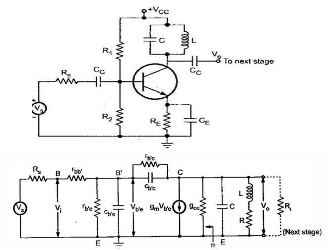
Single Tuned Amplifiers consist of only one Tank Circuit and the amplifying frequency range isdetermined by it. By giving signal to its input terminal of various Frequency Ranges. The Tank Circuit onits collector delivers High Impedance on resonant Frequency, Thus the amplified signal is CompletelyAvailable on the output Terminal. And for input signals other than Resonant Frequency, the tank circuit provides lower impedance, hence most of the signals get attenuated at collector Terminal.

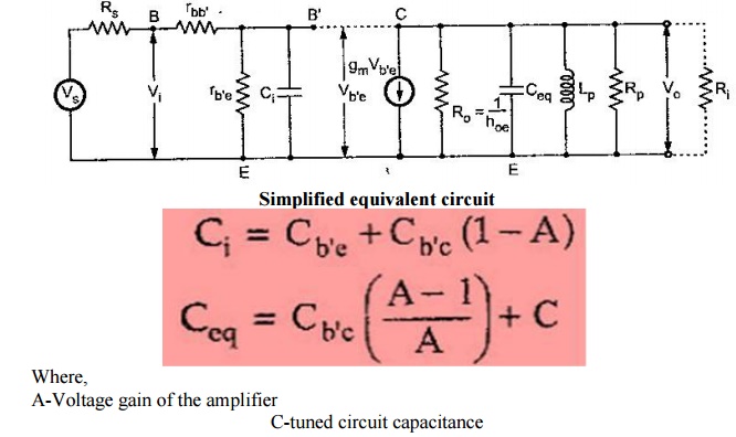
Ri- input resistance of the next stage
R0-output resistance of the generator gmVb‘e
Cc & CE are negligible small
The equivalent circuit is simplified by


