
Similarly, it can be shown that the output voltage V04 due to V4 alone is
V 04= V 4
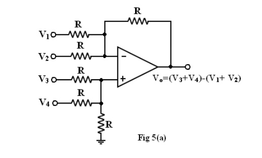
Thus, the output voltage Vo due to all four input voltages is given by
Vo= V01+ V02+ V03+ V04
V o=@V1@V2+ V 3+ V 4
So, the circuit is an adder-subtractor.
Instrumentation Amplifier:
The difference gain of this instrumentation amplifier R, however should never be made zero, as this will make the gain infinity. To avoid such a situation, in a practical circuit, a fixed resistance in series with a potentiometer is used in place of R.
Figure 6(c) shows a differential instrumentation amplifier using Transducer Bridge. The circuit uses a resistive transducer whose resistance changes as a function of the physical quantity to be measured.
The bridge is initially balanced by a dc supply voltage Vdc so that V1=V2. As the physical quantity changes, the resistance RT of the transducer also changes, causing an unbalance in the bridge (V1 ≠V2). This differential voltage now gets amplified by the three op-amp differential instrumentation amplifier.
There are number differential applications of instrumentation amplifier with the transducer bridge, such as temperature indicator, temperature controller, and light intensity meter to name a few.