
The Flyback is the most versatile of all the topologies, allowing the designer to create one or more output voltages, some of which may be opposite in polarity. Flyback converters have gained popularity in battery-powered systems, where a single voltage must be converted into the required system voltages (for example, +5V, +12V and -12V) with very high power conversion efficiency. The basic single-output flyback converter is shown in Figure.
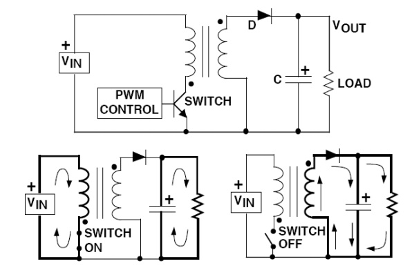
The most important feature of the Flyback regulator is the transformer phasing, as shown by the dots on the primary and secondary windings. When the switch is on, the input voltage is forced across the transformer primary which causes an increasing flow of current through it.
Note that the polarity of the voltage on the primary is dot-negative (more negative at the dotted end), causing a voltage with the same polarity to appear at the transformer secondary (the magnitude of the secondary voltage is set by the transformer seconday-to-primary turns ratio).
The dot-negative voltage appearing across the secondary winding turns off the diode, reventing current flow in the secondary winding during the switch on time. During this time, the load current must be supplied by the output capacitor alone. When the switch turns off, the decreasing current flow in the primary causes the voltage at the dot end to swing positive. At the same time, the primary voltage is reflected to the secondary with the same polarity. The dot-positive voltage occurring across the secondary winding turns on the diode, allowing current to flow into both the load and the output capacitor. The output capacitor charge lost to the load during the switch on time is replenished during the switch off time. Flyback converters operate in either continuous mode (where the secondarycurrent is always >0) or discontinuous mode (where the secondary current falls to zero on each cycle).