
An Astable multivibrator, often called a free running multivibrator, is a rectangular wave generating circuit. Unlike the monostable multivibrator, this circuit does not require an external trigger to change the state of the output, hence the name free running. However, the time during which the output is either high or low is determined by 2 resistors and capacitors, which are externally connected to the 55 timer.
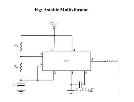
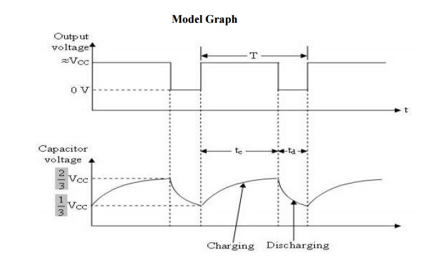
The above figures show the 555 timer connected as an astablemultivibrator and its model graph
Initially, when the output is high :Capacitor C starts charging toward Vcc through RA& RB.However, as soon as voltage across the capacitor equals 2/3 Vcc. Upper comparator triggers the FF & output switches low.
When the output becomes Low:
Capacitor C starts discharging through RB and transistor Q1, when the voltage across C equals 1/3 Vcc, lower comparator output triggers the FF & the output goes High. Then cycle repeats. The capacitor is periodically charged & discharged between 2/3 Vcc & 1/3 Vcc respectively. The time during which the capacitor charges from 1/3 Vcc to 2/3 Vcc equal to the time the output is high & is given by
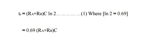
Where RA & RB are in ohms. And C is in farads.
Similarly, the time during which the capacitors discharges from 2/3 Vcc to 1/3 Vcc is equal to the time, the output is low and is given by,

where RB is in ohms and C is in farads.
Thus the total period of the output waveform is
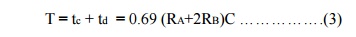
This, in turn, gives the frequency of oscillation as,
Equation 4 indicates that the frequency f0 is independent of the supply voltage Vcc. Often the term duty cycle is used in conjunction with the astable multivibrator. The duty cycle is the ratio of the time tc during which the output is high to the total time period T. It is generally expressed as a percentage.
%duty cycle = (tc / T )* 100
%DC = [(RA+RB)/ /(RA+2RB)] * 100