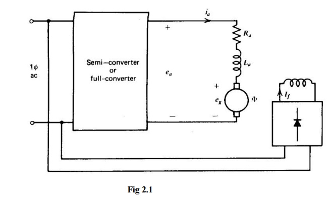
The basic circuit for a single-phase separately excited dc motor drive is shown in Fig. 2.1.The armature voltage is controlled by a semi-converter or full-converter and the field circuit is fed from the ac supply through a diode bridge. The motor current cannot reverse due to the thyristors in the converters. If semi-converters are used, the average output voltage (Ea)is always positive. Therefore power flow (Ea1a) is always positive, that is, from the ac supply to the dc load. In drive system semi-converters, regeneration or reverse power flow from motor to ac supply is not possible. In semi-converters free-wheel (i.e., dissipation of armature inductance energy through the free-wheeling path) takes place when the thyristor blocks.
Single-phase full-wave drives are used for low and medium- horsepower applications as indicated infig2.1.Suchdriveshavepoor speed regulation on open-loop firing angle control. However, with armature voltage or tachometer feedback, good regulation can be achieved.
Basic Equation I
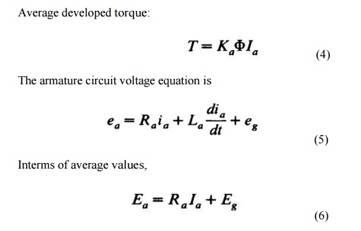
The armature circuit of the de motor is represented by its back voltage eg, armature resistance Ra, and armature inductance LaasshowninFig.2.1.
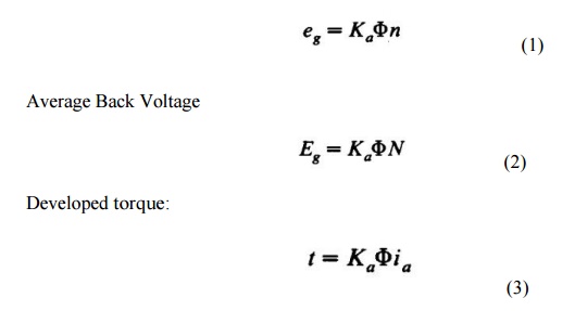
Back voltage:


Note that the inductance La does not absorb any average voltage. From equations 2 and 6, the average speed is

In single-phase converters, the armature voltage ea and current t, change with time. This is unlike the M-G set drive in which both ea and t, are essentially constant. In phase-controlled converters, the armature current ia may not even be continuous. In fact, for most operating conditions, t, is discontinuous. This makes prediction of performance difficult. Analysis is simplified if continuity of armature current can be assumed. Analysis for both continuous and discontinuous current is presented in the following sections

