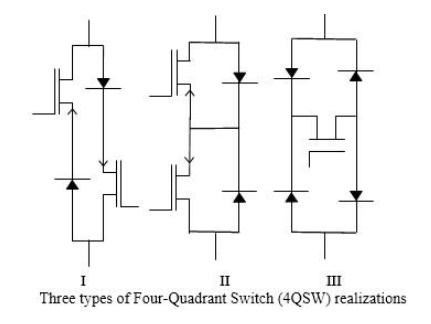
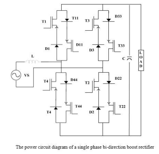
The bi-directional boost converter is the IPQC version of the conventional thyristor dual converters. Their topology is derived from ac-ac matrix converters using four quadrant switches (4QSWs). Since no four-quadrant switch is currently commercially available the realized by embedding a transistor inside a diode bridge or by inverse parallel connections of transistors as shown in Fig (1). Power IGBT employed because they have the advantage so high switching frequency and small pulse and notch widths. Topology of a single-phase bi-directional boost converter using typeI 4QSWs is shown in Fig(2).
In the circuit shown in Fig (2), here are four4QSWs, two in each limb. Each 4QSW comprises two 2QSWs (two quadrant switches), each two-quadrant switch consisting of a IGBTT with series diode, connected in inverse-parallel. The operation of the bi -directional boost converter in boost mode and in a particular quadrant in the V-I plane shown in Fig (3) is determined by the conditioning of the switching states of two sets (IandII) of devices. In the single-phase version each set comprises four IGBTs; set(A) IGBTs–T11,T22,T33,T44 and set(B)I GBTTs-T1,T2,T3,T4. corresponding to the four quadrants in the buck and boost modes pertaining to the rectification and inversion operations


