
All of the switching converters that will be covered in this paper use a form of output voltage regulation known as Pulse Width Modulation (PWM). Put simply, the feedback loop adjusts (corrects) the output voltage by changing the ON time of the switching element in the converter. As an example of how PWM works, we will examine the result of applying a series of square wave pulses to an L-C filter (see Figure).
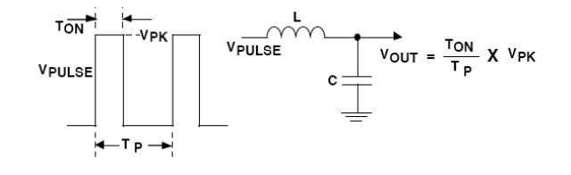
The series of square wave pulses is filtered and provides a DC output voltage that is equal to the peak pulse amplitude multiplied times the duty cycle (duty cycle is defined as the switch ON time divided by the total period). This relationship explains how the output voltage can be directly controlled by changing the ON time of the switch.
Switching Converter Topologies The most commonly used DC-DC converter circuits will now be presented along with the basic principles of operation.