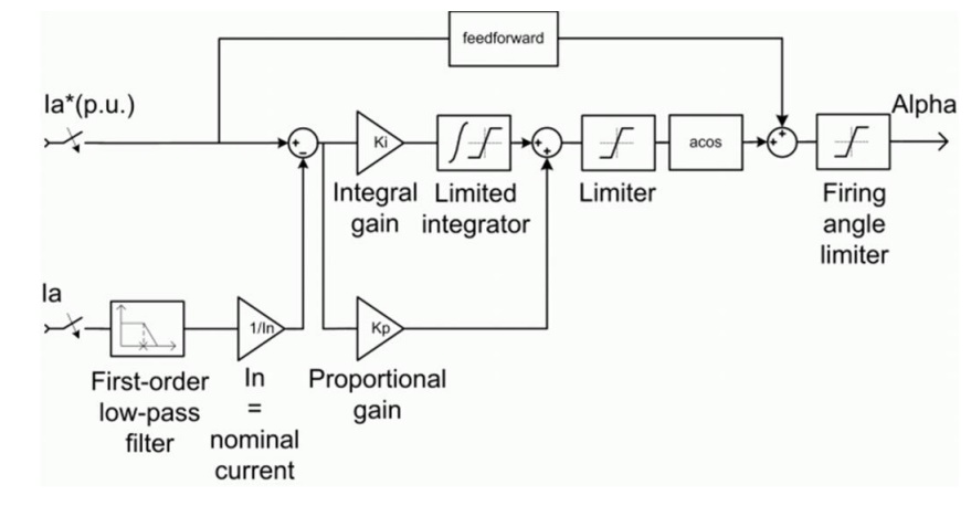
The armature current regulator in the following figure is based on a second PI controller. The regulator controls the armature current by computing the appropriate thyristor firing angle. This generates the rectifier output voltage needed to obtain the desired armature current and thus the desired electromagnetic torque.
The controller takes the current reference (in pu) and the armature current flowing through the motor as inputs. The current reference is either provided by the speed controller during speed regulation or computed from the torque reference provided by the user during torque regulation. This is managed by the "regulation switch" block.
The armature current input is filtered by a first-order low-pass filter. An arccosine function is used to linearize the control system during continuous conduction. To compensate nonlinearities appearing during discontinuous conduction, a feed forward term is added to the firing angle.


