common Mode operation
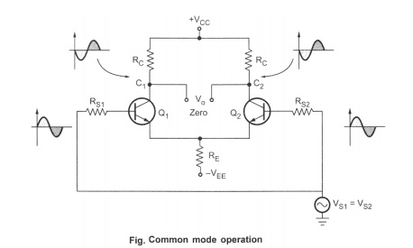
In this mode, the signals applied to the base of Q1 and Q2 are derived from the same source. So the two signals are equal in magnitude as well as in phase. The circuit diagram is shown in the Fig
In phase signal voltages at the bases of Q1 and Q2 causes in phase signal voltages to appear across R E, which add together. Hence R E carries a signal current and provides a negative feedback. This feedback reduces the common mode gain of differential amplifier.

While the two signals causes in phase signal voltages of equal magnitude to appear across the two collectors of Q 1 and Q2. Now the output voltage is the difference between the two collector voltages, which are equal and also same in phase,
Eg. (20) - (20) = 0. Thus the difference output Vo is almost zero, negligibly small. ideally it should be zero.
· Configurations of Differential Amplifier
The differential amplifier, in the difference amplifier stage in the op-amp, can be used in four configurations :
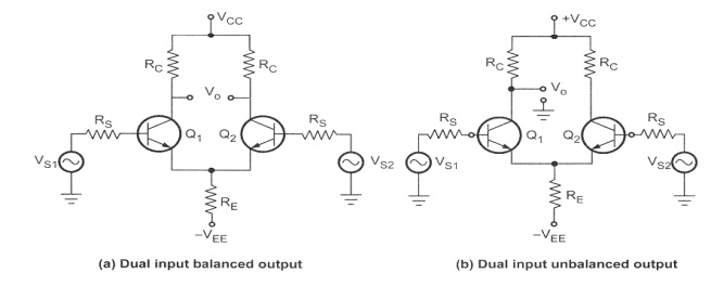
i) Dual input balanced output differential amplifier.
ii) Dual input, unbalanced output differential amplifier.
iii) Single input, balanced output differential amplifier.
iv) Single input, unbalanced output differential amplifier.
The differential amplifier uses two transistors in common emitter configuration. If output is taken between the two collectors it is called balanced output or double ended output. While if the output is taken between one collector with respect to ground it iscalled unbalanced output or single ended output. If the signal is given to both the input terminals it is called dual input, while if the signal is given to only one input terminal and other terminal is grounded it is called single input or single ended input Out of these four configurations the dual input, balanced output is the basic differential amplifier configuration. This is shown in the Fig. (a). The dual input,unbalanced output differential amplifier is shown in the Fig.(b). The single input,balanced output differential amplifier is shown in the Fig (c) and the single input,unbalanced output differential amplifier is shown in the Fig. (d).


