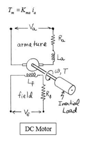
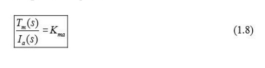
In a armature controlled motor, the field current if is held constant, and the armature current is controlled through the armature voltage Va. In this case, the motor torque increase linearly with the armature current. We write
The transfer function from the input armature current to the resulting motor torque is
Equations (1.8), (1.11) and (1.12) together can be represented by the closed loop block diageam shown below.
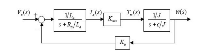
Block diagram reduction gives the transfer unction from the input armature voltage to the resulting speed change.
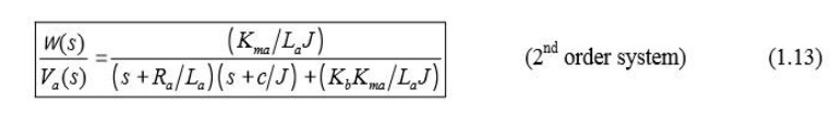
The transfer function from the input armature voltage to the resulting angular position change is ound by multiplying Equation (1.13) by 1/s.
The voltage/current relationship for the armature side of the motor is
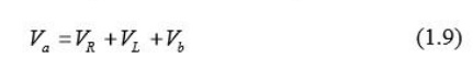
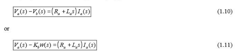
Where Vb represents the “back EMF” induced by the rotation of the armature windings in a magnetic field. The back EMF Vb is proportional to the speed W, i.e. Vb(s) = Kbw(s). Taking Laplace transforms of Eqution (1.9) gives
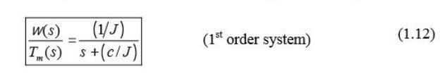
As before, the transfer function rom the input motor torque to rotational speed change is