Let us consider the transistor amplifier as a block box.
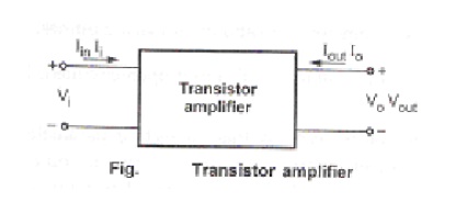
Where, Ii – input current to the amplifier
Vi - input voltage to the amplifier
Io – output current of the amplifier
Vo – output voltage of the amplifier
Input current is an independent variable. Input voltage and output current are dependent variables. Input current and output voltage are independent variables.

This can be written in the equation form as,

The above equation can also be written using alphabetic notations,

Ø Definitions of h-parameter:
The parameters in the above equations are defined as follows:
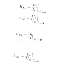
h11 – input resistance with output short-circuited in ohms
h12 – fraction of output voltage at input with input open circuited, it is unitless
h21 – forward current transfer ratio or current gain with output short circuited, it is
unitless
h22 – output admittance with input open circuited in mhos
Ø Benefits of h-parameters:
1. Real numbers at audio frequencies
2. Easy to measure
3. Can be obtained from the transistor static characteristic curve
4. Convenient to use in circuit analysis and design
5. Most of the transistor manufacturers specify the h-parameters
1. h-Parameters for all three configurations:
Transistor can be represented as two port network by making anyone terminal common between input and output. There are three possible configurations in which a transistor can be used, there is a change in terminal voltage and current for different transistor configurations. To designate the type of configuration another subscript is added to h-parameters.
hie = h11e– input resistance in CE configuration
hfb = h21b – short circuit current gain in CB configuration
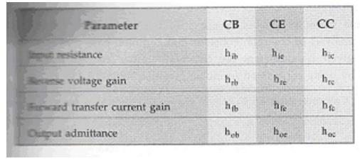
The basic circuit of hybrid model is same for all three configurations, only parameters are different.
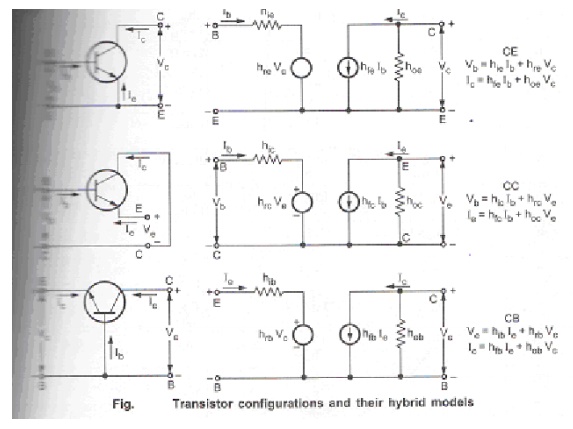
The circuit and equations are valid for either NPN or PNP transistor and are independent of the type of load or method of biasing.
ü Determination of h-parameters from characteristics:
Consider CE configuration, its functional relationship can be defined from the following equations:

The input characteristic curve gives the relationship between input voltage VBE and input current IB for different values of output voltage VCE. The following figure shows the typical input characteristic curve for CE configuration.
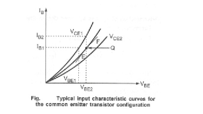
ü Determination of hie and hre from characteristic curve:
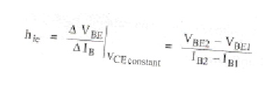
Parameter hie:
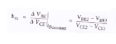
Parameter hre:
The output characteristic curve gives the relationship between output current IC and output voltage VCE for different values of input current IB.
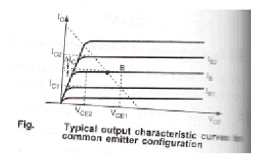
ü Determination of hfe and hoe from output characteristic curve:
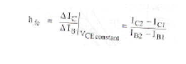
Parameter hfe:
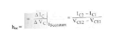
Parameter hoe:
2. Method for analysis of a transistor circuit:
The analysis of transistor circuits for small signal behaviour can be made by following simple guidelines. These guidelines are,
1. Draw the actual circuit diagram
2. Replace coupling capacitors and emitter bypass capacitor by short circuit
3. Replace D.C. source by a short circuit
4. Mark the points B, E, C on the circuit diagram and locate these points as the start of the equivalent circuit
5. Replace the transistor by its h-parameter model
Problem 1:
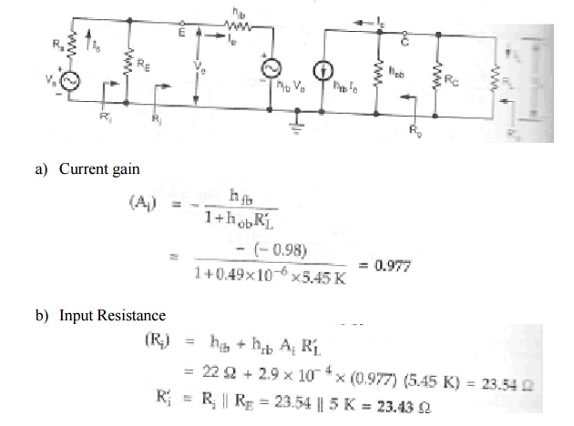
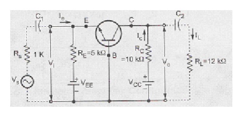
For the common base circuit shown in figure, transistor parameters are hib = 22Ω,
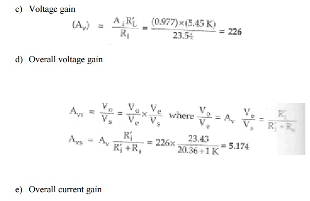
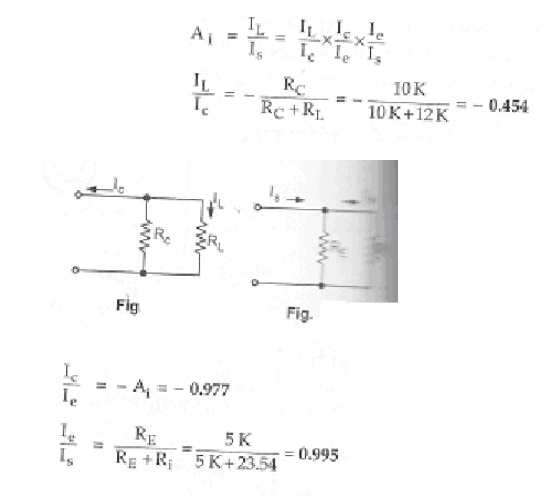
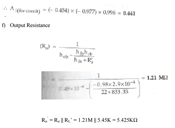
hfb = -0.98, hob = 0.49µA/V, hrb = 2.9*10-4. Calculate the values of input resistance, output resistance, current gain and voltage gain for the given circuit.
Solution:
Change the given figure into h-parameter equivalent model.
