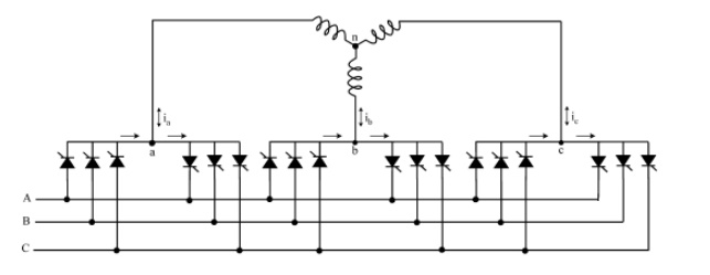
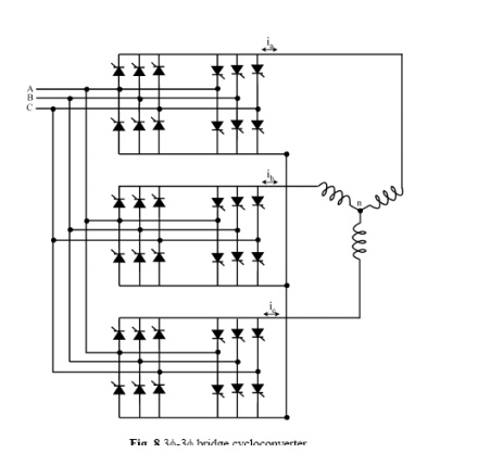
If the outputs of 3 3f-1f converters of the same kind are connected in wye or delta and if the output voltages are 2p/3 radians phase shifted from each other, the resulting converter is a three- phase to three-phase (3f-3f) cycloconverter. The resulting cycloconverters are shown in Figs. 7 and 8 with wye connections. If the three converters connected are half-wave converters, then the new converter is called a 3f-3f half-wave cycloconverter. If instead, bridge converters are used, then the result is a 3f-3f bridge cycloconverter. 3f-3f half-wave cycloconverter is also called a 3-pulse cycloconverter or an 18-thyristor cycloconverter. On the other hand, the 3f-3f bridge cycloconverter is also called a 6-pulse cycloconverter or a 36-thyristor cycloconverter. The operation of each phase is explained in the previous section.
The three-phase cycloconverters are mainly used in ac machine drive systems running three- phase synchronous and induction machines. They are more advantageous when used with a synchronous machine due to their output power factor characteristics. A cycloconverter can supply lagging, leading, or unity power factor loads while its input is always lagging. A synchronous machine can draw any power factor current from the converter. This characteristic operation matches the cycloconverter to the synchronous machine. On the other hand, induction machines can only draw lagging current, so the cycloconverter does not have an edge compared to the other converters in this aspect for running an induction machine. However, cycloconverters are used in Scherbius drives for speed control purposes driving wound rotor induction motors.
Cycloconverters produce harmonic rich output voltages, which will be discussed in the following sections. When cycloconverters are used to run an ac machine, the leakage inductance of the machine filters most of the higher frequency harmonics and reduces the magnitudes of the lower order harmonics.
1. Blocked Mode and Circulating Current Mode:
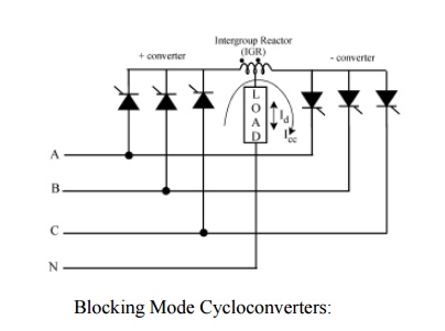
The operation of the cycloconverters is explained above in ideal terms. When the load current is positive, the positive converter supplies the required voltage and the negative converter is disabled. On the other hand, when the load current is negative, then the negative converter supplies the required voltage and the positive converter is blocked. This operation is called the blocked mode operation, and the cycloconverters using this approach are called blocking mode cycloconverters.
However, if by any chance both of the converters are enabled, then the supply is short-circuited. To avoid this short circuit, an intergroup reactor (IGR) can be connected between the converters as shown in Fig. 9. Instead of blocking the converters during current reversal, if they are both enabled, then a circulating current is produced. This current is called the circulating current. It is unidirectional because the thyristors allow the current to flow in only one direction. Some cycloconverters allow this circulating current at all times. These are called circulating current cycloconverters.
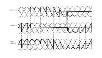
The operation of these cycloconverters was explained briefly before. They do not let circulating current flow, and therefore they do not need a bulky IGR. When the current goes to zero, both positive and negative converters are blocked. The converters stay off for a short delay time to assure that the load current ceases. Then, depending on the polarity, one of the converters is enabled. With each zero crossing of the current, the converter, which was disabled before the zero crossing, is enabled. A toggle flip-flop, which toggles when the current goes to zero, can be used for this purpose. The operation waveforms for a three-pulse blocking mode cycloconverter are given in Fig.
The blocking mode operation has some advantages and disadvantages over the circulating mode operation. During the delay time, the current stays at zero distorting the voltage and current waveforms. This distortion means complex harmonics patterns compared to the circulating mode cycloconverters. In addition to this, the current reversal problem brings more control complexity. However, no bulky IGRs are used, so the size and cost is less than that of the circulating current case. Another advantage is that only one converter is in conduction at all times rather than two. This means less losses and higher efficiency.
2. Circulating Current Cycloconverters:
In this case, both of the converters operate at all times producing the same fundamental output voltage. The firing angles of the converters satisfy the firing angle condition (Eq. 3), thus whenone converter is in rectification mode the other one is in inversion mode and vice versa. If both of the converters are producing pure sine waves, then there would not be any circulating current because the instantaneous potential difference between the outputs of the converters would be zero. In reality, an IGR is connected between the outputs of two phase controlled converters (in either rectification or inversion mode).
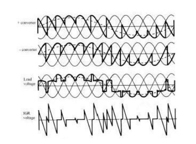
The voltage waveform across the IGR can be seen in Fig. 11d. This is the difference of the instantaneous output voltages produced by the two converters. Note that it is zero when both of the converters produce the same instantaneous voltage. The center tap voltage of IGR is the voltage applied to the load and it is the mean of the voltages applied to the ends of IGR, thus the load voltage ripple is reduced.
2.1Circulating mode
The circulating current cycloconverter applies a smoother load voltage with less harmonics compared to the blocking mode case. Moreover, the control is simple because there is no current reversal problem. However, the bulky IGR is a big disadvantage for this converter. In addition to this, the number of devices conducting at any time is twice that of the blocking mode converter. Due to these disadvantages, this cycloconverter is not attractive.
The blocked mode cycloconverter converter and the circulating current cycloconverter can be combined to give a hybrid system, which has the advantages of both. The resulting cycloconverter looks like a circulating mode cycloconverter circuit, but depending on the polarity of the output current only one converter is enabled and the other one is disabled as with the blocking mode cycloconverters. When the load current decreases below a threshold, both of the converters are enabled. Thus, the current has a smooth reversal. When the current increases above a threshold in the other direction, the outgoing converter is disabled. This hybrid cycloconverter operates in the blocking mode most of the time so a smaller IGR can be used. The efficiency is slightly higher than that of the circulating current cycloconverter but much less than the blocking mode cycloconverter. Moreover, the distortion caused by the blocking mode operation disappears due to the circulating current operation around zero current. Moreover, the control of the converter is still less complex than that of the blocking mode cycloconverter.
