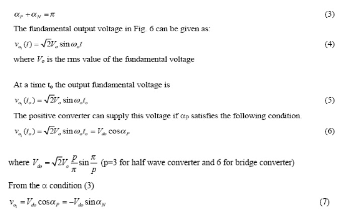
There are two kinds of three-phase to single-phase (3f-1f) cycloconverters: 3f-1f half-wave cycloconverter (Fig. 1) and 3f-1f bridge cycloconverter (Fig. 2). Like the 1f-1f case, the 3f-1f cycloconverter applies rectified voltage to the load. Both positive and negative converters can generate voltages at either polarity, but the positive converter can only supply positive current and the negative converter can only supply negative current. Thus, the cycloconverter can operate in four quadrants: (+v, +i) and (-v, -i) rectification modes and (+v, -i) and (-v, +i) inversion modes. The modulation of the output voltage and the fundamental output voltage
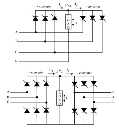
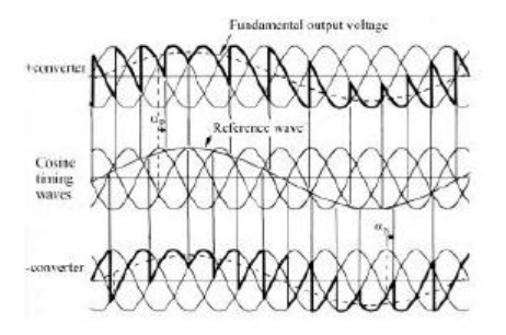
The polarity of the current determines if the positive or negative converter should be supplying power to the load. Conventionally, the firing angle for the positive converter is named aP, and that of the negative converter is named aN. When the polarity of the current changes, the converter previously supplying the current is disabled and the other one is enabled. The load always requires the fundamental voltage to be continuous. Therefore, during the current polarity reversal, the average voltage supplied by both of the converters should be equal. Otherwise, switching from one converter to the other one would cause an undesirable voltage jump. To prevent this problem, the converters are forced to produce the same average voltage at all times. Thus, the following condition for the firing angles should be met