Design of stator winding:
Stator winding is made up of former wound coils of high conductivity copper of diamond shape. These windings must be properly arranged such that the induced emf in all the phases of the coils must have the same magnitude and frequency. These emfs must have same wave shape and be displaced by 1200 to each other. Single or double layer windings may be used depending on the requirement. The three phase windings of the synchronous machines are always connected in star with neutral earthed. Star connection of windings eliminates the 3rd harmonics from the line emf.
Double layer winding: Stator windings of alternators are generally double layer lap windings either integral slot or fractional slot windings. Full pitched or short chorded windings may be employed. Following are the advantages and disadvantages of double layer windings.
Advantages:
(i) Better waveform: by using short pitched coil
(ii) Saving in copper: Length of the overhang is reduced by using short pitched coils
(iii) Lower cost of coils: saving in copper leads to reduction in cost
(iv) Fractional slot windings: Only in double layer winding, leads to improvement in waveform
Disadvantages:
(i) Difficulty in repair: difficult to repair lower layer coils
(ii) Difficulty in inserting the last coil: Difficulty in inserting the last coil of the windings
Number of Slots:
The number of slots are to be properly selected because the number of slots affect the cost and performance of the machine. There are no rules for selecting the number of slots. But looking into the advantages and disadvantages of higher number of slots, suitable number of slots per pole per phase is selected. However the following points are to be considered for the selection of number of slots.
(a)
Advantages:
(i) Reduced leakage reactance
(ii) Better cooling
(iii) Decreased tooth ripples
Disadvantages:
(i) Higher cost
(ii) Teeth becomes mechanically weak
(iii) Higher flux density in teeth
(b) Slot loading must be less than 1500 ac/slot
(c) Slot pitch must be with in the following limitations
(i) Low voltage machines ≤ 3.5 cm
(ii) Medium voltage machines up to 6kV ≤ 5.5 cm
(iv) High voltage machines up to 15 kV ≤ 7.5 cm
Considering all the above points number of slots per pole phase for salient pole machines may be taken as 3 to 4 and for turbo alternators it may be selected as much higher of the order of 7 to 9 slots per pole per phase In case of fractional slot windings number of slots per pole per phase may be selected as fraction 3.5.
Turns per phase:
Turns per phase can be calculated from emf equation of the alternator.
Induced emf Eph = 4.44 f Φ TphKw
Hence turns per phase Tph = Eph / 4.44 f ΦKw
Eph = induced emf per phase
Zph = no of conductors/phase in stator
Tph = no of turns/phase
kw = winding factor may assumed as 0.955
Conductor cross section: Area of cross section of stator conductors can be estimated from the stator current per phase and suitably assumed value of current density for the stator windings.
Sectional area of the stator conductor as = Is / δs where δs is the current density in stator windings
Is is stator current per phase
A suitable value of current density has to be assumed considering the advantages and disadvantages.
Advantages of higher value of current density:
(i) reduction in cross section
(ii) reduction in weight
(iii) reduction in cost
Disadvantages of higher value of current density
(i) increase in resistance
(ii) increase in cu loss
(iii) increase in temperature rise
(iv) reduction in efficiency
Hence higher value is assumed for low voltage machines and small machines. Usual value of current density for stator windings is 3 to 5 amps/mm2.
Stator coils:
Two types of coils are employed in the stator windings of alternators. They are single turn bar coils and multi turn coils. Comparisons of the two types of coils are as follows
(i) Multi turn coil winding allows greater flexibility in the choice of number of slots than single turn bar coils.
(ii) Multi turn coils are former wound or machine wound where as the single turn coils are hand made.
(iii) Bending of top coils is involved in multi turn coils where as such bends are not required in single turn coils.
(iv) Replacing of multi turn coils difficult compared to single turn coils.
(v) Machine made multi turn coils are cheaper than hand made single turn coils.
(vi) End connection of multi turn coils are easier than soldering of single turn coils.
(vii) Full transposition of the strands of the single turn coils are required to eliminate the eddy current loss.
(viii) Each turn of the multi turn winding is to be properly insulated thus increasing the amount of insulation and reducing the space available for the copper in the slot.
From the above discussion it can be concluded that multi turn coils are to be used to reduce the cost of the machine. In case of large generators where the stator current exceeds 1500 amps single turn coils are employed.
Single turn bar windings:
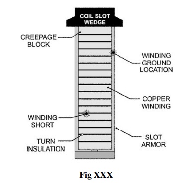
The cross section of the conductors is quite large because of larger current. Hence in order to eliminate the eddy current loss in the conductors, stator conductors are to be stranded. Each slot of the stator conductor consists of two stranded conductors as shown in Fig XXX. The dimensions of individual strands are selected based on electrical considerations and the manufacturing requirements. Normally the width of the strands is assumed between 4 mm to 7 mm. The depth of the strands is limited based on the consideration of eddy current losses and hence it should not exceed 3mm. The various strand of the bar are transposed in such a way as to minimize the circulating current loss.

Multi turn coils:
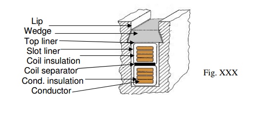
Multi turn coils are former wound. These coils are made up of insulated high conductivity copper conductors. Mica paper tape insulations are provided for the portion of coils in the slot and varnished mica tape or cotton tape insulation is provide on the over hang portion. The thickness of insulation is decided based on the voltage rating of the machine. Multi turn coils are usually arranged in double layer windings in slots as shown in Fig XXX.

Dimensions of stator slot:
Width of the slot = slot pitch – tooth width
The flux density in the stator tooth should not exceed 1.8 to 2.0 Tesla. In salient pole alternators internal diameter is quite large and hence the flux density along the depth of the tooth does not vary appreciably. Hence width of the tooth may be estimated corresponding to the permissible flux density at the middle section of the tooth. The flux density should not exceed 1.8 Tesla. However in case of turbo alternators variation of flux density along the depth of the slot is appreciable and hence the width of the tooth may be estimated corresponding to the flux density at the top section of the tooth or the width of the tooth at the air gap. The flux density at this section should not exceed 1.8 Tesla.
For salient pole alternator:
Flux density at the middle section =
Flux / pole /( width of the tooth at the middle section x iron length x number of teeth per pole arc) Number of teeth per pole arc = pole arc/slot pitch
For turbo alternators:
Flux density at the top section =
Flux / pole /( width of the tooth at the top section x iron length x number of teeth per pole pitch) As the 2/3rd pole pitch is slotted the number of teeth per pole pitch = 2/3 x pole pitch/( slot pitch at top section) Slot width = slot pitch at the top section – tooth width at the top section.
Once the width of the slot is estimated the insulation required width wise and the space available for conductor width wise can be estimated.
Slot insulation width wise:
(i) Conductor insulation
(ii) Mica slot liner
(iii) Binding tape over the coil
(iv) Tolerance or clearance
Space available for the conductor width wise = width of the slot – insulation width wise
We have already calculated the area of cross section of the conductor. Using above data on space available for the conductor width wise depth of the conductor can be estimated. Now the depth of the slot may be estimated as follows.
Depth of the slot:
(i) Space occupied by the conductor = depth of each conductor x no. of conductor per slot
(ii) Conductor insulation
(iii) Mica slot liner
(iv) Mica or bituminous layers to separate the insulated conductors
(v) Coil separator between the layers
(vi) Wedge
(vii) Lip
(viii) Tolerance or clearance
Mean length of the Turn:
The length of the mean turn depends on the following factors
(i) Gross length of the stator core: Each turn consists of two times the gross length of stator core.
(ii) Pole pitch: The over hang portion of the coils depend upon the coil span which in turn depends upon the pole pitch.
(iii) Voltage of the machine: The insulated conductor coming out of the stator slot should have straight length beyond the stator core which depends upon the voltage rating of the machine.
(iv) Slot dimension: Length per turn depends on the average size of the slot.
Hence mean length of the turn in double layer windings of synchronous machines is estimated as follows.
lmt = 2l + 2.5 τp+ 5 kV + 15 cm

