CC CONFIGURATION
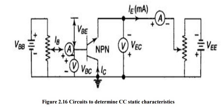
In common collector configuration circuit is shown in figure. Here collector is grounded and it is used as the common terminal for both input and output. It is also called as grounded collector configuration. Base is used as a input terminal whereas emitter is the output terminal.
Ø Input Characteristics
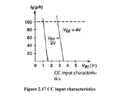
It is defined as the characteristic curve drawn between input voltage to input current whereas output voltage is constant.
To determine input characteristics, the emitter base voltage VEB is kept constant at zero and base current IB is increased from zero by increasing VBC.This is repeated for higher fixed values of VCE.A curve is drawn between base current and base emitter voltage at constant collector base voltage is shown in figure2.17.
Ø Output Characteristics
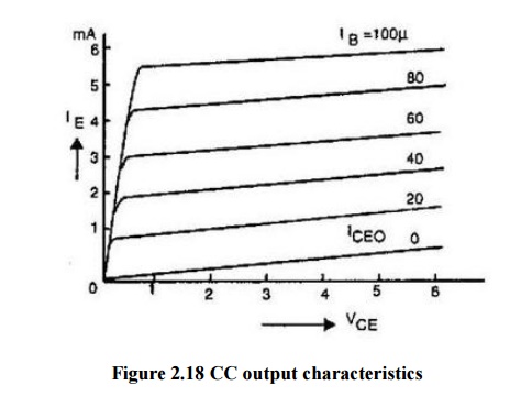
It is defined as the characteristic curve drawn between output voltage to output current whereas input current is constant.
To determine output characteristics, the base current IB is kept constant at zero and emitter current IE is increased from zero by increasing VEC. This is repeated for higher fixed values of IB.
From the characteristic it is seen that for a constant value of IB, IE is independent of VEB and the curves are parallel to the axis of VEC.
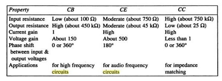
A comparison of CB, CE and CC Configurations