Things to observe:
1. Flip-flop implementation: reset priority, event, rising edge sensitive.
2. If and case -- sequential statements -- are valid only within a process.
3. Concurrent assignment is a ``process.''
4. Semantics of a process: sensitivity list, assignments:
5. b <= a;
6. c <= b;
does not behave as it would in C.
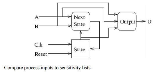
7. VHDL architecture broken into three processes:
a) State storage.
b) Next state generation.
c) Output generation.

-- VHDL for serial comparator. The inputs a and b are input lsb first.
-- The Mealy machine uses rising edge sensitive flip-flops and an
-- asynchronous active low reset.
--
-- The output is 1 if b > a, otherwise 0.
library ieee;
use ieee.std_logic_1164.all;
entity comparator is port
(a, b, clk, reset : in std_logic; o : out std_logic );
end comparator;
architecture process_defn of comparator is
-- Two states needed.
type state_type is (S0, S1); -- State assignment.
attribute enum_encoding : string; attribute enum_encoding of state_type :
type is "0 1";
signal state, next_state : state_type;
-- For convenience, concatenate a and b. signal inputs : std_logic_vector (1 downto 0);
begin
-- Concurrent assignment executes the rhs changes.
-- Concatenate a and b into inputs.
inputs <= a & b;
-- Processes execute whenever something on their sensitivity list
-- changes. All assignments take place when the process exits.
--
-- This process implements the D flip-flop.
state_register : process (clk, reset) begin
-- If/else construct only valid within a process. if (reset = '0') then
state <= S0;
elsif (clk'event AND clk = '1') then state <= next_state;
end if; end process;
-- This process computes the next state.
next_state_process : process (inputs, state) begin
case state is
when S0 =>
if (inputs = "01") then next_state <= S1;
else
next_state <= S0; end if;
when S1 =>
if (inputs = "10") then next_state <= S0;
else
next_state <= S1; end if;
end case; end process;
-- This process computes the output.
output_process : process (inputs, state) begin
case state is
when S0 =>
if (inputs = "01") then o <= '1';
else
o <= '0'; end if;
when S1 =>
if (inputs = "10") then o <= '0';
else
o <= '1'; end if;
end case; end process;
end process_defn;
A test bench is a virtual environment used to verify the correctness or soundness of a design or model (e.g., a software product).
The term has its roots in the testing of electronic devices, where an engineer would sit at a lab bench with tools of measurement and manipulation, such as oscilloscopes, multimeters, soldering irons, wire cutters, and so on, and manually verify the correctness of the device under test.
In the context of software or firmware or hardware engineering, a test bench refers to an environment in which the product under development is tested with the aid of a collection of testing tools. Often, though not always, the suite of testing tools is designed specifically for the product under test.
A test bench or testing workbench has four components.
1.INPUT: The entrance criteria or deliverables needed to perform work
2.PROCEDURES TO DO: The tasks or processes that will transform the input into the output
3.PROCEDURES TO CHECK: The processes that determine that the output meets the standards.
4.OUTPUT: The exit criteria or deliverables produced from the workbench
Free yourself from the time-consuming process of writing Verilog and VHDL test benches by hand. Generate them graphically from timing diagrams using SynaptiCAD's TestBencher Pro, WaveFormer Pro, DataSheet Pro, VeriLogger, and BugHunter Pro products. With 3 levels of test bench generation you can choose the product that meets the type and complexity of your testing needs. For basic test benches, WaveFormer can import waveform data from just about anywhere and generate stimulus vector test benches in a matter of minutes. BugHunter and VeriLogger also support basic stimulus generation and also include a fast, interactive unit-level testing environment. For more testbench flexibility, the Reactive Test Bench generation Option can be added to generate single timing diagram based test benches that react to the model under test. And for the most complex testing needs, TestBencher Pro generates test benches that are complete bus-functional models that monitor and react during runtime simulations.

WaveFormer Pro and DataSheet Pro stimulus code example
BugHunter Pro and VeriLogger Extreme interactive testing example
WaveFormer Pro, Data Sheet Pro, and BugHunter come with the basic stimulus test bench generation features. Drawn waveforms are used to generate stimulus models. The BugHunter features are tightly integrated into the simulation environment to allow quick interactive testing of design models.

· Reactive Test Bench Option example
The Reactive Test Bench Generation Option is an option that can be added to WaveFormer Pro, DataSheet Pro, and the BugHunter Pro products. This option allows users to create self-testing test benches from a single timing diagram which generate error reports and react to the model under test during simulation. It also enables generation of "clocked test benches" that update stimulus based on one or more clock signals.

· TestBencher Pro code example
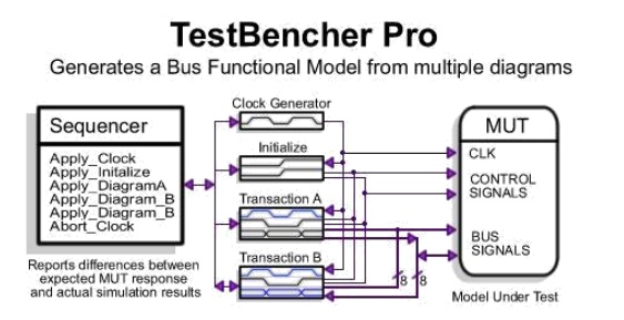
The highest level of testbench generation is provided by TestBencher Pro, which allows a user to design bus functional models using multiple timing diagrams to define transactors and a sequencer process to apply the diagram transactions. TestBencher can be added to BugHunter or purchased as a standalone product.

