INDUCTION MOTORS
Introduction:
Induction motors are the ac motors which are employed as the prime movers in most of the industries. Such motors are widely used in industrial applications from small workshops to large industries. These motors are employed in applications such as centrifugal pumps, conveyers, compressors crushers, and drilling machines etc.
Constructional Details:
Similar to DC machines an induction motor consists of a stationary member called stator and a rotating member called rotor. However the induction motor differs from a dc machine in the following aspects.
1. Laminated stator
2. Absence of commutator
3. Uniform and small air gap
4. Practically almost constant speed
The AC induction motor comprises two electromagnetic parts:
• Stationary part called the stator
• Rotating part called the rotor
The stator and the rotor are each made up of
• An electric circuit, usually made of insulated copper or aluminum winding, to carry current
• A magnetic circuit, usually made from laminated silicon steel, to carry magnetic flux
The stator
The stator is the outer stationary part of the motor, which consists of
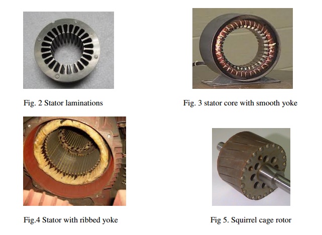
• The outer cylindrical frame of the motor or yoke, which is made either of welded sheet steel, cast iron or cast aluminum alloy.
• The magnetic path, which comprises a set of slotted steel laminations called stator core pressed into the cylindrical space inside the outer frame. The magnetic path is laminated to reduce eddy currents, reducing losses and heating.
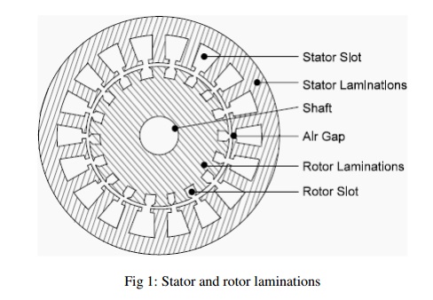
• A set of insulated electrical windings, which are placed inside the slots of the laminated stator. The cross-sectional area of these windings must be large enough for the power rating of the motor. For a 3-phase motor, 3 sets of windings are required, one for each phase connected in either star or delta. Fig 1 shows the cross sectional view of an induction motor. Details of construction of stator are shown in Figs

The rotor
Rotor is the rotating part of the induction motor. The rotor also consists of a set of slotted silicon steel laminations pressed together to form of a cylindrical magnetic circuit and the electrical circuit. The electrical circuit of the rotor is of the following nature
Squirrel cage rotor consists of a set of copper or aluminum bars installed into the slots, which are connected to an end-ring at each end of the rotor. The construction of this type of rotor along with windings resembles a ‘squirrel cage’. Aluminum rotor bars are usually die-cast into the rotor slots, which results in a very rugged construction. Even though the aluminum rotor bars are in direct contact with the steel laminations, practically all the rotor current flows through the aluminum bars and not in the lamination
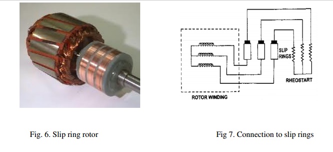
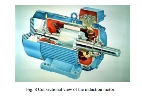
Wound rotor consists of three sets of insulated windings with connections brought out to three slip rings mounted on one end of the shaft. The external connections to the rotor are made through brushes onto the slip rings as shown in fig 7. Due to the presence of slip rings such type of motors are called slip ring motors. Sectional view of the full induction motor is shown in Fig. 8
Some more parts, which are required to complete the constructional details of an induction motor, are:
• Two end-flanges to support the two bearings, one at the driving-end and the other at the non driving-end, where the driving end will have the shaft extension.
• Two sets of bearings to support the rotating shaft,
• Steel shaft for transmitting the mechanical power to the load
• Cooling fan located at the non driving end to provide forced cooling for the stator and rotor
• Terminal box on top of the yoke or on side to receive the external electrical connections
Figure 2 to show the constructional details of the different parts of induction motor.


Introduction to Design
The main purpose of designing an induction motor is to obtain the complete physical dimensions of all the parts of the machine as mentioned below to satisfy the customer specifications. The following design details are required.
1. The main dimensions of the stator.
2 Details of stator windings.
3. Design details of rotor and its windings
4. Performance characteristics.
In order to get the above design details the designer needs the customer specifications Rated output power, rated voltage, number of phases, speed, frequency, connection of stator winding, type of rotor winding, working conditions, shaft extension details etc.
In addition to the above the designer must have the details regarding design equations based on which the design procedure is initiated, information regarding the various choice of various parameters, information regarding the availability of different materials and the limiting
values of various performance parameters such as iron and copper losses, no load current, power factor, temperature rise and efficiency

