
PID Controllers
Proportional controllers
– pure gain or attenuation
Integral controllers
– integrate error
Derivative controllers
– differentiate error
Proportional Controller
U = Kp e
o Controller input is error (reference output)
o Controller output is control signal
o P controller involves only a proportional gain (or attenuation)
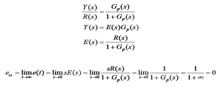
Integral Controller
o Integral of error with a constant gain
o Increase system type by 1
o Infinity steady-state gain
o Eliminate steady-state error for a unit step input
Integral Controller
Derivative Control
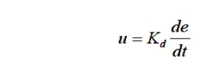
o Differentiation of error with a constant gain
o Reduce overshoot and oscillation
o Do not affect steady-state response
o Sensitive to noise
Controller Structure
o Single controller
o P controller, I controller, D controller
o Combination of controllers
o PI controller, PD controller
o PID controller
Controller Performance
o P controller
o PI controller
o PD Controller
o PID Controller
Design of PID Controllers
o Based on the knowledge of P, I and D
– trial and error
– manual tuning
– simulation
Design of PID Controllers
o Time response measurements are particularly simple.
o A step input to a system is simply a suddenly applied input - often just a constant voltage applied through a switch.
o The system output is usually a voltage, or a voltage output from a transducer measuring the output.
o A voltage output can usually be captured in a file using a C program or a Visual Basic program.
o You can use responses in the time domain to help you determine the transfer function of a system.
o First we will examine a simple situation. Here is the step response of a system. This is an example of really "clean" data, better than you might have from measurements. The input to the system is a step of height 0.4. The goal is to determine the transfer function of the system.