
Modeling of electrical system
Electrical circuits involving resistors, capacitors and inductors are considered. The behavior of such systems is governed by Ohm’s law and Kirchhoff’s laws.
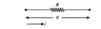
Resistor: Consider a resistance of ‘R’ Ω carrying current ‘I’ Amps as shown in Fig (a), then the voltage drop across it is v = R I
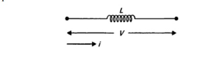
Inductor: Consider an inductor ― L’ H carrying current ’i ’ Amps as shown in Fig (a), then the voltage drop across it can be written as v = L di/dt
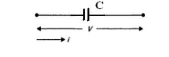
Capacitor: Consider a capacitor ’C’ F carrying current ’i ’ Amps as shown in Fig (a), then the voltage drop across it can be written as v = (1/C)∫ i dt
Steps for modeling of electrical system
o Apply Kirchhoff‗s voltage law or Kirchhoff‗s current law to form the differential equations describing electrical circuits comprising of resistors, capacitors, and inductors.
o Form Transfer Functions from the describing differential equations.
o Then simulate the model.
Example
Electrical systems
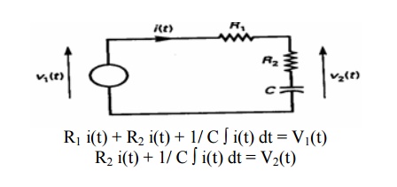
LRC circuit. Applying Kirchhoff‗s voltage law to the system shown. We obtain the following equation;
Resistance circuit
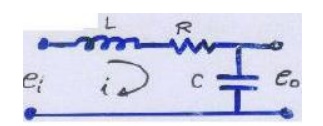
L(di /dt) + Ri + 1/ C ∫ i(t) dt =ei …………………….. (1)
1/ C ∫ i(t) dt =e0 ……………………………………….. (2)
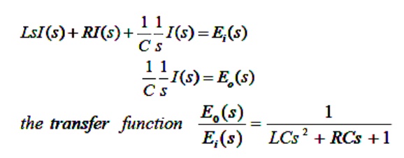
Equation (1) & (2) give a mathematical model of the circuit. Taking the L.T. of equations (1)&(2), assuming zero initial conditions, we obtain
Armature-Controlled dc motors
The dc motors have separately excited fields. They are either armature-controlled with fixed field or field-controlled with fixed armature current. For example, dc motors used in instruments employ a fixed permanent-magnet field, and the controlled signal is applied to the armature terminals.
Consider the armature-controlled dc motor shown in the following figure.
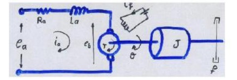
Ra = armature-winding resistance, ohms
La = armature-winding inductance, henrys
ia = armature-winding current, amperes
if = field current, a-pares
ea = applied armature voltage, volt
eb = back emf, volts
θ = angular displacement of the motor shaft, radians
T = torque delivered by the motor, Newton*meter
J = equivalent moment of inertia of the motor and load referred to the motor shaft kg.m2
f = equivalent viscous-friction coefficient of the motor and load referred to the motor shaft. Newton*m/rad/s
T = k1 ia ψ where ψ is the air gap flux, ψ = kf if , k1 is constant
For the constant flux
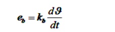
Where Kb is a back emf constant -------------- (1)
The differential equation for the armature circuit
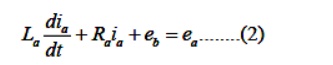
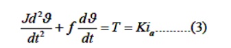
The armature current produces the torque which is applied to the inertia and friction; hence
Assuming that all initial conditions are condition are zero/and taking the L.T. of equations (1),
(2) & (3), we obtain
Kps θ (s) = Eb (s)
(Las+Ra ) Ia(s) + Eb (s) = Ea (s) (Js2 +fs)
θ (s) = T(s) = K Ia(s)
The T.F can be obtained is
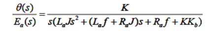
Analogous Systems
Let us consider a mechanical (both translational and rotational) and electrical system as shown in the fig.
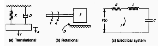
From the fig (a)
We get M d2 x / dt2 + D d x / dt + K x = f
From the fig (b)
We get M d2 θ / dt2 + D d θ / dt + K θ = T
From the fig (c)
We get L d2 q / dt2 + R d q / dt + (1/C) q = V(t)
Where q = ∫i dt
They are two methods to get analogous system. These are (i) force- voltage (f-v) analogy and (ii) force-current (f-c) analogy
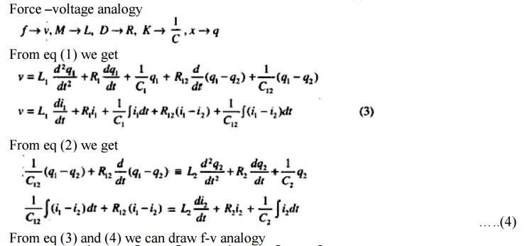
Force –Voltage Analogy
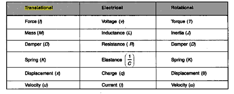
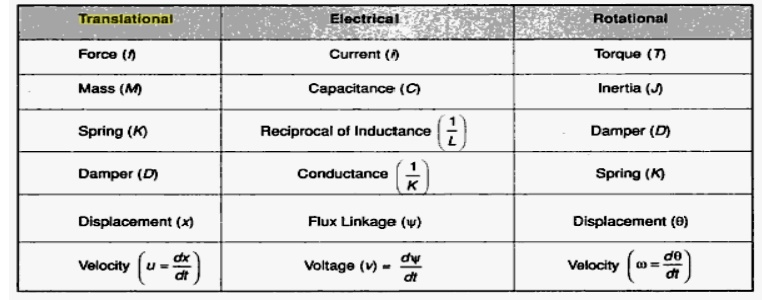
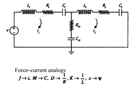
Force – Current Analog
Problem
1. Find the system equation for system shown in the fig. And also determine f-v and f-i analogies
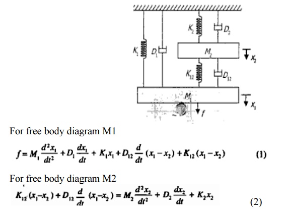
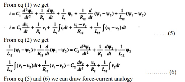
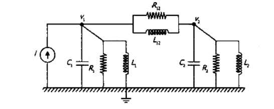
The system can be represented in two forms:
1. Block diagram representation
2. Signal flow graph