Block diagram
A pictorial representation of the functions performed by each component and of the flow of signals.
Basic elements of a block diagram
o Blocks
o Transfer functions of elements inside the blocks
o Summing points
o Take off points
o Arrow
Block diagram
A control system may consist of a number of components. A block diagram of a system is a pictorial representation of the functions performed by each component and of the flow of signals.
The elements of a block diagram are block, branch point and summing point.
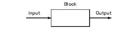
Block
In a block diagram all system variables are linked to each other through functional blocks. The functional block or simply block is a symbol for the mathematical operation on the input signal to the block that produces the output.
Summing point
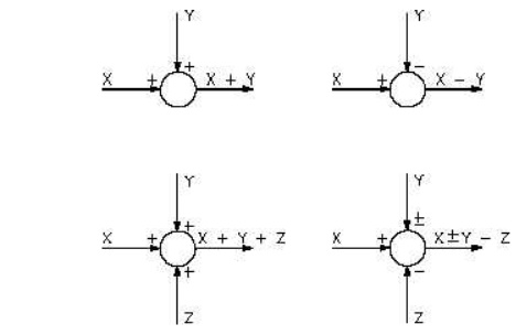
Although blocks are used to identify many types of mathematical operations, operations of addition and subtraction are represented by a circle, called a summing point. As shown in Figure a summing point may have one or several inputs. Each input has its own appropriate plus or minus sign.
A summing point has only one output and is equal to the algebraic sum of the inputs.
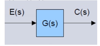
A takeoff point is used to allow a signal to be used by more than one block or summing point. The transfer function is given inside the block
• The input in this case is E(s)
• The output in this case is C(s)
C(s) = G(s) E(s)
Functional block – each element of the practical system represented by block with its T.F.
Branches – lines showing the connection between the blocks
Arrow – associated with each branch to indicate the direction of flow of signal
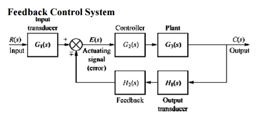
Closed loop system
Summing point – comparing the different signals
Take off point – point from which signal is taken for feed back
Advantages of Block Diagram Representation
o Very simple to construct block diagram for a complicated system
o Function of individual element can be visualized
o Individual & Overall performance can be studied
o Over all transfer function can be calculated easily.
Disadvantages of Block Diagram Representation
o No information about the physical construction
o Source of energy is not shown
Simple or Canonical form of closed loop system
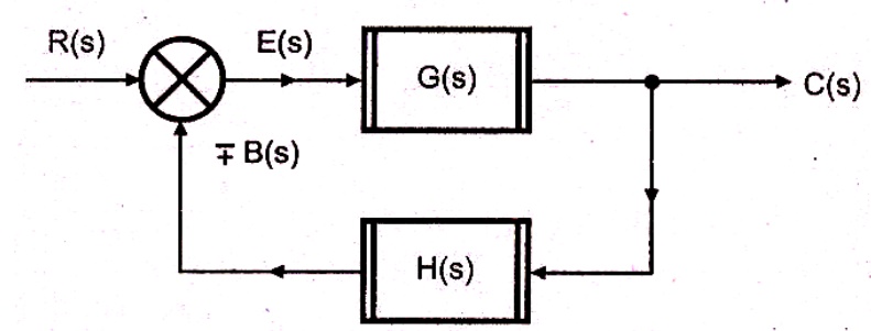
R(s) – Laplace of reference input r(t)
C(s) – Laplace of controlled output c(t)
E(s) – Laplace of error signal e(t)
B(s) – Laplace of feed back signal b(t)
G(s) – Forward path transfer function
H(s) – Feed back path transfer function
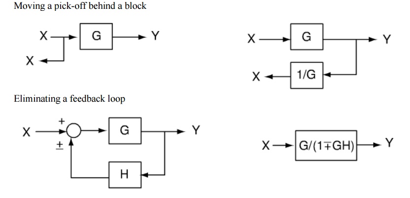
Block diagram reduction technique
Because of their simplicity and versatility, block diagrams are often used by control engineers to describe all types of systems. A block diagram can be used simply to represent the composition and interconnection of a system. Also, it can be used, together with transfer functions, to represent the cause-and-effect relationships throughout the system. Transfer Function is defined as the relationship between an input signal and an output signal to a device.
Block diagram rules
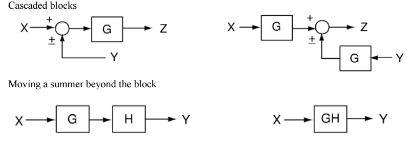
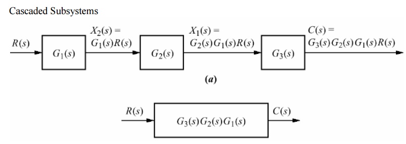
Cascaded blocks
Procedure to solve Block Diagram Reduction Problems
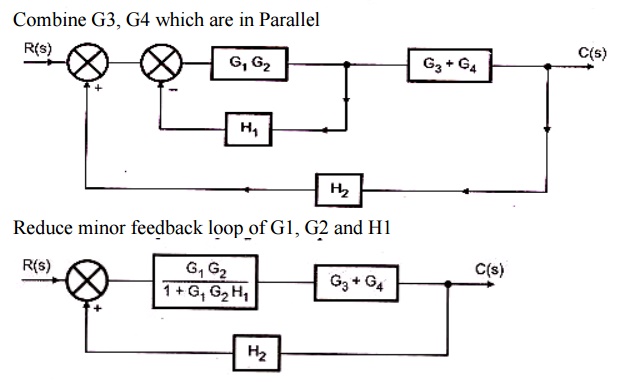
Step 1: Reduce the blocks connected in series Step
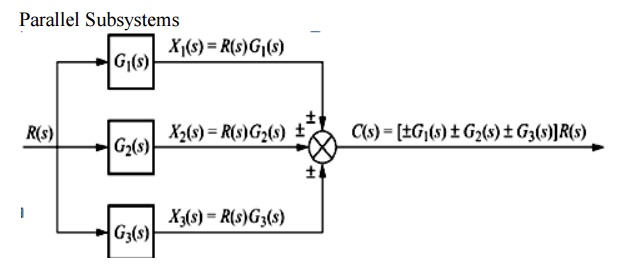
2: Reduce the blocks connected in parallel Step 3: Reduce the minor feedback loops
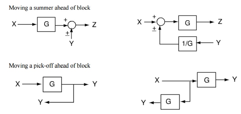
Step 4: Try to shift take off points towards right and Summing point towards left
Step 5: Repeat steps 1 to 4 till simple form is obtained
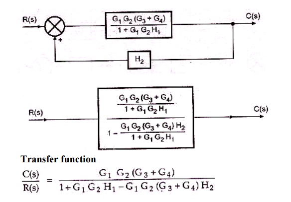
Step 6: Obtain the Transfer Function of Overall System
Problem 1
1. Obtain the Transfer function of the given block diagram
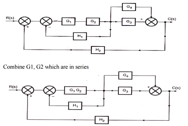
2. Obtain the transfer function for the system shown in the fig
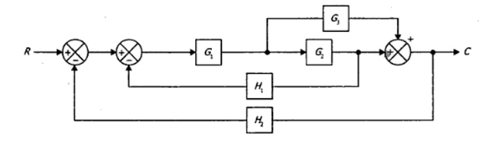
3. Obtain the transfer function C/R for the block diagram shown in the fig
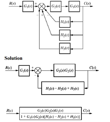
Solution
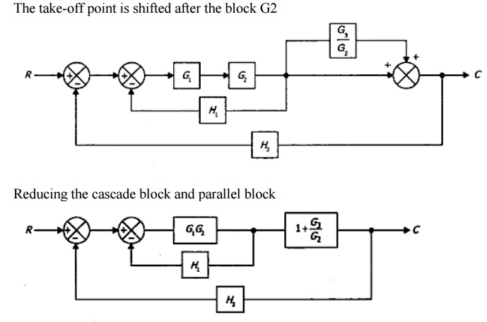
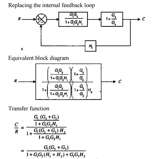
The take-off point is shifted after the block G2