So far we have considered dc resistive network in which currents and voltages were independent of time. More specifically, Voltage (cause input) and current (effect output) responses displayed simultaneously except for a constant multiplicative factor (VR). Two basic passive elements namely, inductor and capacitor are introduced in the dc network. Automatically, the question will arise whether or not the methods developed in lesson-3 to lesson-8 for resistive circuit analysis are still valid. The voltage/current relationship for these two passive elements are defined by the derivative (voltage across the inductor
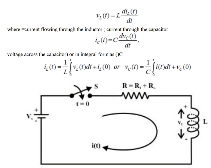
Our problem is to study the growth of current in the circuit through two stages, namely; (i) dc transient response (ii) steady state response of the system
D.C Transients: The behavior of the current and the voltage in the circuit switch is closed until it reaches its final value is called dc transient response of the concerned circuit. The response of a circuit (containing resistances, inductances, capacitors and switches) due to sudden application of voltage or current is called transient response. The most common instance of a transient response in a circuit occurs when a switch is turned on or off –a rather common event in an electric circuit.
Growth or Rise of current in R-L circuit
To find the current expression (response) for the circuit shown in fig. 10.6(a), we can write the KVL equation around the circuit
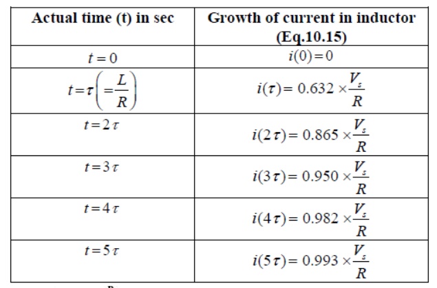
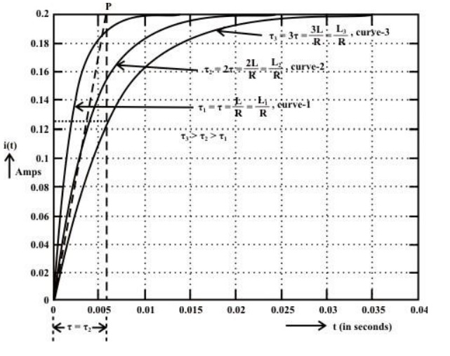
The table shows how the current i(t) builds up in a R-L circuit.
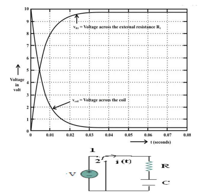
Consider network shown in fig. the switch k is moved from position 1 to 2 at reference time t = 0.
Now before switching take place, the capacitor C is fully charged to V volts and it discharges through resistance R. As time passes, charge and hence voltage across capacitor i.e. Vc decreases gradually and hence discharge current also decreases gradually from maximum to zero exponentially.
After switching has taken place, applying kirchoff’s voltage law,

Where VR is voltage across resistor and VC is voltage across capacitor.
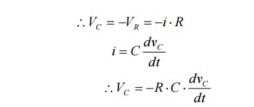
Above equation is linear, homogenous first order differential equation. Hence rearranging we have,

Integrating both sides of above equation we have

Now at t = 0, VC =V which is initial condition, substituting in equation we have,
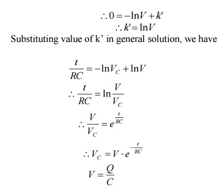
Where Q is total charge on capacitor
Similarly at any instant, VC = q/c where q is instantaneous charge.
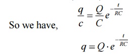
Thus charge behaves similarly to voltage across capacitor.
Now discharging current i is given by
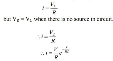
but VR = VC when there is no source in circuit.
The above expression is nothing but discharge current of capacitor. The variation of this current with respect to time is shown in fig.
This shows that the current is exponentially decaying. At point P on the graph. The current value is (0.368) times its maximum value. The characteristics of decay are determined by values R and C, which are 2 parameters of network.
For this network, after the instant t = 0, there is no driving voltage source in circuit, hence it is called undriven RC circuit.
