1. INTRODUCTION
A chopper is a static device that converts fixed DC input voltage to variable output voltage directly. Chopper are mostly used in electric vehicle, mini haulers.
Chopper are used for speed control and braking. The systems employing chopper offer smooth control, high efficiency and have fast response
If we consider the converter to be loss less then the input power is equal to the output power and is given by
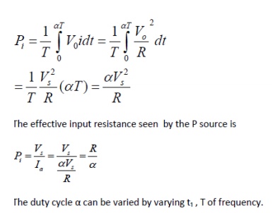
Constant frequency operation:
1)The chopping period T is kept constant and on time is varied. The pulse width modulation ,the width of the pulse is varied.
2) Variable frequency operation, the chopping frequency f is varied. Frequency modulation, either on time or off time is kept constant.
This type of control generate harmonics at unpredictable frequency and filter design is often difficult.
2. TYPES OF CHOPPER:
2.1 FIRST QUADRANT OR TYPE A CHOPPER:
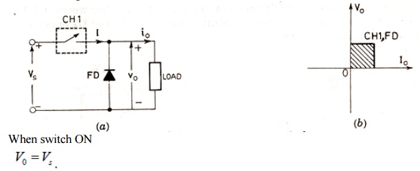
Current i₀ flows in the same direction when switch off.
V₀=0, i₀=0
So, average value of both the load and the current are positive.
2.3 SECOND QUADRANT OR TYPE B CHOPPER:
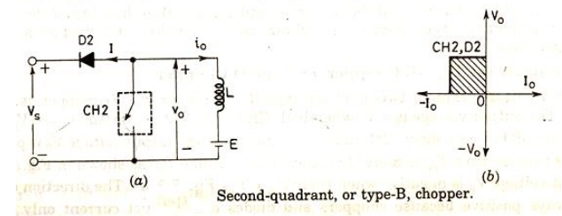
When switch are closed the load voltage E drives current through L and switch. During on T
L stores energy.
When switch off 0 V
exceeds source voltage s V

Diode D₂ is forward biased.power is fed back to supply. As V₀is more than sourse voltage. So such chopper is called step up chopper.

So current is always negative and V₀ is always positive.
3.4 TWO QUADRANT TYPE A CHOPPER OR, TYPE C CHOPPER:
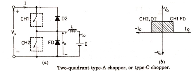
Both the switches never switch ON simultaneously as it lead direct short circuit of the supply.
Now when sw2 is closed or FD is on the output voltage V₀ is zero. When sw1 is ON or diode D conducts output voltage is V₀ is +Vs‟
CURRENT ANANLYSIS:
When CH1 is ON current flows along i0. When CH1 is off current continues to flow along i0 as FD is forward biased. So i0 is positive.
Now when CH2 is ON current direction will be opposite to i0. When sw2 is off D2 turns ON.
Load current is –i0. So average load voltage is always positive. Average load current may be positive or negative.
3.5 TWO QUADRANT TYPE B CHOPPER, OR TYPE D CHOPPER:
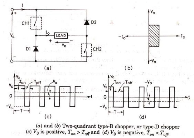
When CH1 and CH2 both are on then V0=Vs.
When CH1 and CH2 are off and D1 and D2 are on V 0=-Vs.
The direction of current is always positive because chopper and diode can only conduct in the direction of arrow shown in fig.
Average voltage is positive when Ton>Toff
3.6 FOUR QUADRANT CHOPPER, OR TYPE E CHOPPER

FIRST QUADRANT:
CH4 is kept ON
CH3 is off
CH1 is operarted V0=Vs
i0 = positive
when CH1 is off positive current free wheels through CH4,D2 so V0 and I2 is in first quadrant.
SECOND QUADRANT:
CH1,CH3,CH4 are off.
CH2 is operated.
Reverse current flows and I is negative through L CH2 D4 and E.
When CH2 off D1 and D4 is ON and current id fed back to source. So is more than source voltage

As i0 is negative and V0 is positive, so second quadrant operation.
THIRD QUADRANT:
CH1 OFF, CH2 ON
CH3 operated. So both V0 and i0 is negative.
When CH3 turned off negative current freewheels through CH2 and D4.
FOURTH QUADRANT:
CH4 is operated other are off.
Positive current flows through CH4 E L D2.
Inductance L stores energy when current fed to source through D3 and D2.V0 is negative.
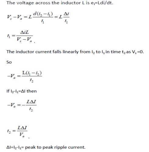
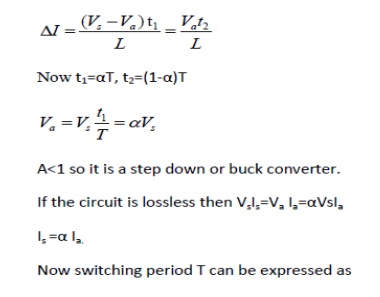
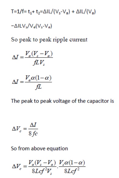
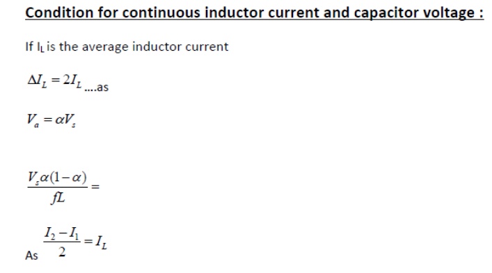
4. STEADY STATE ANALYSIS OF PRACTICAL BUCK CHOPPER:
