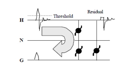
A surge arrester is a device to protect electrical equipment from over-voltage transients caused by external (lightning) or internal (switching) events. Also called a surge protection device (SPD) ortransient voltage surge suppressor (TVSS), this class of device is used to protect equipment in power transmission and distribution systems. (For consumer equipment protection, different products called surge protectors are used.)
To protect a unit of equipment from transients occurring on an attached conductor, a surge arrester is connected to the conductor just before it enters the equipment. The surge arrester is also connected toground and functions by routing energy from an over-voltage transient to ground if one occurs, while isolating the conductor from ground at normal operating voltages. This is usually achieved through use of a varistor, which has substantially different resistances at different voltages.
Surge arresters are not generally designed to protect against a direct lightning strike to a conductor, but rather against electrical transients resulting from lightning strikes occurring in the vicinity of the conductor. Lightning which strikes the earth results in ground currents which can pass over buried conductors and induce a transient that propagates outward towards the ends of the conductor. The same kind of induction happens in overhead and above ground conductors which experience the passing energy of an atmospheric EMP caused by the lightening flash. Surge arresters only protect against induced transients characteristic of a lightning discharge's rapid rise-time and will not protect against electrification caused by a direct strike to the conductor. Transients similar to lightning-induced, such as from a high voltage system's fault switching, may also be safely diverted to ground; however, continuous overcurrents are not protected against by these devices. The energy in a handled transient is substantially less than that of a lightning discharge; however it is still of sufficient quantity to cause equipment damage and often requires protection.
Without very thick insulation, which is generally cost prohibitive, most conductors running more than a minimal distance, say greater than about 50 feet, will experience lightning-induced transients at some time during use. Because the transient is usually initiated at some point between the two ends of the conductor, most applications install a surge arrester just before the conductor lands in each piece of equipment to be protected. Each conductor must be protected, as each will have its own transient induced, and each SPD must provide a pathway to earth to safely divert the transient away from the protected component. The one notable exception where they are not installed at both ends is in high voltage distribution systems. In general, the induced voltage is not sufficient to do damage at the electric generation end of the lines; however, installation at the service entrance to a building is key to protecting downstream products that are not as robust.
Surge Diverters operation
The event we commonly call a surge is more accurately defined as a high voltage transient or impulse. Surge diverters are designed to divert the impulse away from the sensitive electronic system. That’s why the term diverter is more appropriate – it better describes the function of this device. Surge diverter products commonly use one or more of several electronic components. These include metal oxide varistors (MOVs), silicon avalanche diodes (SADs), and gas tubes. There are differences in how each functions but the intent is the same divert a part of the harmful impulse energy away from the computer or system being protected.

All surge diverters have a voltage threshold, called a “clamping voltage”, at which they began to conduct. Above that threshold, impulses are shunted across the diverter to another pathway. When the impulse voltage once again falls below the threshold, the diverter stops conducting. Surge diverters also have a “clamping response” time or the time required for the device to respond to an impulse. The amount of energy each is capable of handling without being destroyed is also a consideration. Due to these factors, each type of component used in surge diverters has unique advantages and disadvantages. MOVs have a high clamping voltage (300 to 500 volts) and a slow response time.
This means that in best case scenarios, voltage impulses of less than 500 volts usually enter the computer system unimpeded. In addition, higher voltage events with very fast rise times may pass by the MOV before it is able to respond. And while MOVs can handle a significant amount of energy, they are physically degraded each time they clamp. This characteristic alters their future performance and ultimately leads to physical failure.
These disadvantages have led to the use of the silicon avalanche diode (SAD) either in conjunction with the MOV or in standalone applications. Compared to MOVs, SADs have a faster response time and are not subject to the physical degradation that characterizes MOVs design. The overall energy handling ability of the SAD, however, is not as high, and an impulse that merely degrades and MOV may cause outright destruction of the SAD. To overcome this disadvantage, many surge diverter manufacturers whose designs use standalone SADs will parallel multiple SADs to increase the overall energy handling capability of the protector.
Industry authorities often vigorously debate the effectiveness of this design method. Gas tubes are comparatively slow and have a high clamp voltage. However, they handle almost unlimited amounts of energy. Some surge diverter designs have employed gas tubes as the final line of “brute force” protection to spare the lives of the other surge diverter components in the presence of a catastrophic powerline disturbance. In fact, many surge diverter designs incorporate paralleled MOVs, SADs, and/or gas tubes in an effort to improve performance by combining the relative strengths of each particular component

