BLPM motor is classified on the basis of number of phase windings and the number of pulses given to the devices during each cycle.
1. One phase winding one pulse BLPM motor
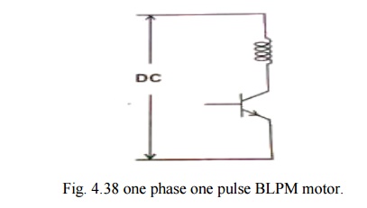
The stator has one phase winding as shown in fig4.38.
It is connected to the supply through a power semiconductor switch. When the rotor position sensor is influenced by say n pole flux, the stator operates and the rotor developed a torque. When the RPS is under the influence of S pole, the transistor is in off state. The rotor gets torque whenever the rotor position is under the influence of n pole.
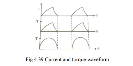
The current and torque are approximated as sinusoidally varying as shown in fig. 4.39.
Advantage
v One transistor and one position sensor is sufficient.
v Inertia should be such that the rotor rotates continuously.
v Utilization of transistor and winding are less than 50%.
2. One phase two pulse BLPM motor
Stator has only one winding. It is connected to DC three wire supply through two semiconductor devices as shown in fig. 4.40.
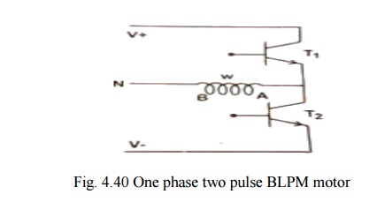
There is only one position sensor. When the position sensor is under the N-pole influence,T1 is in on-state and T2 is in off-state. When it is under the influence of S-pole, T2 is on and T1 is off.
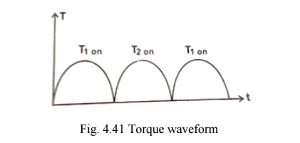
In the first case, the winding carries current from A to B and when T2 is on, the winding carries current from B to A. The polarity of the flux setup by the winding gets alerted depending upon the position of the rotor. This provides the unidirectional torque as shown in fig. 4.41.
Advantages
v Winding utilization is better.
v Torque developed is more uniform.
Demerit
v Transistor utilization is less
v The current needs a 3-wire dc supply.
3. Two phase winding and two pulse BLPM motor
Stator has two phase windings which are displaced y 180° electrical. Electrical connections are as shown in fig. 4.42. It makes use of two semiconductor switches.
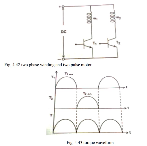
Performance of this type is similar to one phase 2 pulse BLPM motor. Torque waveform are as shown in fig. 4.43. However it requires two independent phase windings.
Merit
v Better torque waveform.
Demerit
v Their utilization is only 50% which is less.
v Cabling with rotor position sensor should be made proper.
4. Three phase winding and three pulse BLPM motor
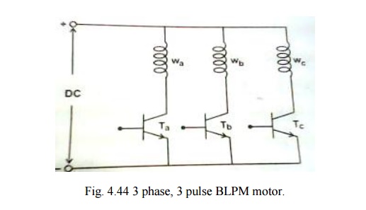
The stator has 3Φ windings as shown in fig. 4.44. Whose areas are displaced by 120°elec. apart. Each phase windings is controlled by a semiconductor switch which is operated depending upon the position of the rotor. Three position sensors are required for this purpose.
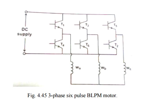
5. Three phase six pulse BLPM motor
Most commonly used. It has 3 phase windings and six witching devices as shown in fig. 4.45.
