Stepping motor is a digital actuator which moves in steps of θs in response to input pulses. such incremental motion results in the following limitations of the stepper motor
Limited resolution
As θs is the smallest angle through which the stepper motor can move, this has an effect on position accuracy of incremental servo system employing stepper motors because the stepper motor cannot position the load to an accuracy finer than θs.
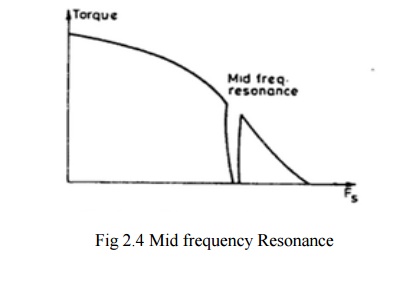
Mid frequency Resonance
A phenomenon in which the motor torque suddenly drops to a low value at certain pulse frequencies as in fig

A new principal known as micro stepping control has been developed with a view of overcoming the above limitation .It enables the stepping motor to move through a tiny micro step of size ∆ θs << θs full step angle is response to input pulses.
1. Principle of micro stepping
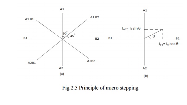
Assume a two phase stepper motor operating in ‗one phase ON‘ sequence. Assume also that only B2 winding is On and carrying current IB2 = IR, the rated phase current. All the other winding are OFF. In this state the stator magnetic field is along the positive real axis as show in fig (a). Naturally the rotor will also as be in θ = 0° position.
When the next input pulse comes, B2 is switched OFF while A1 is switched ON.In this condition IA1= IR while all the phase current are zero. As a result the stator magnetic field rotates through 90® in counter clockwise direction as show in fig (a).
The rotor follows suit by rotating through 90° in the process of aligning itself with stator magnetic field. Thus with a conventional controller the stator magnetic field rotates through 90° when a new input pulse is received causing the rotor to rotate full step.
However in micro stepping we want the stator magnetic field to rote through a small angle θs << 90° in respect to input pulse. This is achieved by modulating the current through
B2 and A1 winding as show in fig (b) such that
IA1= IR sin θ
IB1= IR cos θ
Then the resulting stator magnetic field will be at an angle θ ° with respect to the positive real axis. consequently the rotor will rotate through an angle θs << 90° .
This method of modulating current through stator winding so as to obtain rotation of stator magnetic field through a small angle θ °


