HYSTERISIS TYPE CURRENT REGULATION
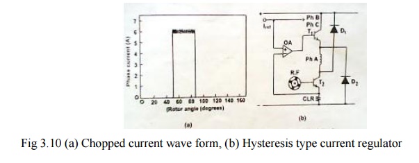
As by this control circuit current is maintained more or less constant like ―hysteresis‖ throughout the conduction period in each phase it is known as hysteresis type control. Fig 3.10 (a) shows the current waveform controlled by the hysteresis type current regulator. The schematic arrangement of the control circuit is shown in fig 3.10 (b).

Principle of operation
As shown in fig. 3.10(b) the transducer (a tachogenerator) is connected from the rotor and then the output signal from the transducer is given as a feedback signal at the base of transistor T2. From the emitter of transistor T2, the portion of the feedback signal (current) is fed at the input of the operational amplifier (O.A). There it is compared with the reference current and correspondingly after amplification the feedback signal is given at the base of transistor T1. This signal in combination with collector current will flow from the emitter of transistor T1 through A phase winding of the machine. Thus the current through A phase winding can be controlled depending on the requirement. CLR is the resistance for limiting the current as per the design.
As the current reference increase the torque increases. At low currents the torque is roughly proportional to current squared but at higher current it becomes more nearly linear. At very high currents, saturation decreases the torque per ampere again. This type of control produces a constant-torque type of characteristics.
With loads whose torque increases monotonically with speed, such as fans and blowers, speed adjustment is possible without tachometer feedback but general feedback is needed to provide accurate speed control. In some cases the pulse train from the soft position sensor may be used for speed feedback, but only at relative high speeds.
As low speeds, a larger number of pulses per revolution are necessary and this can be generated by an optical encoder or resolver for alternatively by phase-locking a high frequency oscillator to the pulses of the commutation sensor. System with resolver-feedback or high-resolution optical encoders can work right down to zero speed.
The ―hysteresis type‖ current regulator may require current transducers of wide bandwidth, but the SR drive has the advantage that they can be grounded at one end with the other connected to the negative terminal of the lower phase leg switch. The sensors used are shunts or hall-effect sensors or sensefets with in build current sensing.

