Digital-To-Analogue (D/A) Conversion
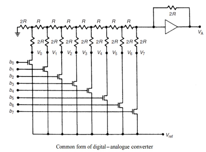
Digital-to-analogue conversion is much simpler to achieve than analogue-to-digital conversion and the cost of building the necessary hardware circuit is considerably less. It is required wherever a digitally processed signal has to be presented to an analogue control actuator or an analogue signal display device. A common form of digital-to-analogue converter is illustrated in Figure 5.24. This is shown with 8 bits for simplicity of explanation, although in practice 10 and 12 bit D/A converters are used more frequently. This form of D/A converter consists of a resistor-ladder network on the input to an operational amplifier

V0 to V7 are set at either the reference voltage level Vref or at zero volts according to whether an associated switch is open or closed. Each switch is controlled by the logic level of one of the bits 0 – 7 of the 8 bit binary signal being converted. A particular switch is open if the relevant binary bit has a value of 0 and closed if the value is 1. Consider for example a digital signal with binary value of 11010100. The values of V7 to V0 are therefore:


